Purpose of an Entity Relationship ER Diagram
An ERD is created to answer fundamental questions about enterprise information. Instead of focusing on database tables or software implementation, it focuses on the logical structures.
- What business objects exist?
- Which information must be stored?
- How are business objects related?
- Which business rules govern those relationships?
- Which information is shared across applications?
- Where is the authoritative source of each data object?
- What is the impact of changing a data structure?
Why Organizations Build ERDs
Entity Relationship Diagrams ERDs are developed throughout the software development lifecycle and enterprise architecture process. They provide a stable enterprise information model that remains valuable, regardless of implementation technology.
| Solution |
Purpose of the ERD |
| CRM |
Model customers, contacts, accounts, and interactions. |
| ERP |
Model products, suppliers, orders, invoices, and inventory. |
| HRM |
Model employees, departments, contracts, and positions. |
| Financial Systems |
Model accounts, transactions, and ledgers. |
| Healthcare Systems |
Model patients, treatments, and medical records. |
| Government Systems |
Model citizens, permits, and registrations. |
| Insurance Systems |
Model policies, claims, and customers. |
| Banking Platforms |
Model customers, accounts, loans, and payments. |
| Data Warehouses |
Define enterprise information structures. |
| Master Data Management |
Identify enterprise master entities. |
| API Platforms |
Define resource models. |
| Data Lakes |
Organize metadata and business entities. |
| AI Platforms |
Create consistent training datasets. |
| Digital Twins |
Model enterprise information objects. |
| Enterprise Architecture |
Connect information with business and technology. |
Although implementation technologies continuously evolve, the need for a consistent enterprise information model remains unchanged.
Consequences of Not Having an ERD
Organizations that do not maintain an enterprise information model frequently experience structural information problems. These issues often become visible during application integration, digital transformation, cloud migration, or analytics initiatives.
- Multiple definitions of the same customer.
- Duplicate data stored across different systems.
- Conflicting business terminology.
- Complex and expensive system integrations.
- Poor data quality.
- Inconsistent reporting.
- Difficult application migrations.
- Unclear ownership of enterprise information.
- Low confidence in AI and analytics.
- Higher software maintenance costs.
- Increased cybersecurity risks.
- Limited impact analysis capabilities.
Many enterprise transformation projects fail because organizations understand their applications better than their information.
Core Concepts
The diagram of Entity Relationship ER Model is based on a relatively small number of fundamental concepts. These concepts form the vocabulary used by Enterprise Architects, Data Architects, Database Engineers, and Software Engineers to model enterprise information consistently.
Entity
An Entity represents a distinguishable business object about which information is stored.
An entity represents what exists, not how information is physically stored in a database.
Typical examples include:
- Customer
- Employee
- Product
- Supplier
- Invoice
- Order
- Application
- Business Capability
- Asset
- Device
Entity Type
An Entity Type defines a category of similar business objects that share the same characteristics, attributes, and relationships. Every entity instance belongs to exactly one entity type.
Examples of Entity Types:
- Customer
- Employee
- Product
- Invoice
Entity Types define their logical structure of information independently of database implementation.
Entity Instance
An Entity Instance represents one specific occurrence of an Entity Type.
Entity Type
Customer
Entity Instances
Customer #10045
Customer #10046
Customer #10047
The Entity Type defines the structure, while the Entity Instance contains the actual business data.
Entity Class
An Entity Class is the conceptual definition of a group of entities within a modeling language, metamodel, or information architecture. Although the terms Entity Class and Entity Type are often used interchangeably, an Entity Class generally represents the reusable definition from which Entity Types are derived.
Within Dragon1, Entity Classes are reusable architectural building blocks that can be specialized and connected to Business Objects, Applications, APIs, Databases, and other architectural concepts.
- Customer
- Employee
- Product
- Business Service
- Database
- API
Entity Set
An Entity Set is the complete collection of all Entity Instances belonging to a particular Entity Type. Conceptually, an Entity Set corresponds to the rows of a relational database table, although the Entity Relationship ER Model itself remains independent of implementation technology.
Customer Entity Set
Customer #1001
Customer #1002
Customer #1003
Customer #1004
Attributes
An Attribute represents a characteristic or property of an Entity Type. Attributes describe the information that must be stored about an entity
Example:
Customer
CustomerID
Name
Email
DateOfBirth
Status
Attributes should describe intrinsic business characteristics rather than implementation details.
Attribute Domain
Every attribute belongs to an Attribute Domain. A domain specifies the set of valid values that an attribute may contain, thereby improving data quality and consistency across enterprise systems.
| Attribute |
Domain |
| BirthDate |
Valid calendar dates |
| Email |
RFC-compliant email format |
| CountryCode |
ISO 3166 country codes |
| Currency |
ISO 4217 currency codes |
| Status |
Active, Inactive or Suspended |
Simple Attributes
A Simple Attribute contains a single indivisible value. It cannot be decomposed into smaller meaningful components.
- Name
- Age
- Salary
- Price
- Gender
Composite Attributes
A Composite Attribute consists of multiple logical sub-attributes that together represent one business concept.
Address
Street
House Number
Postal Code
City
Country
Composite attributes improve semantic clarity and support logical decomposition of complex information.
Multivalued Attributes
A Multivalued Attribute can contain multiple values for a single Entity Instance.
Customer
Phone Numbers
• Mobile
• Home
• Office
In normalized relational databases, multivalued attributes are typically modeled as separate Entity Types connected through relationships.
Derived Attributes
A Derived Attribute is calculated from one or more other attributes instead of being stored directly.
Age derived from DateOfBirth
OrderTotal
derived from
OrderLines
Derived attributes are generally calculated dynamically unless performance requirements justify physical storage.
Keys
Keys uniquely identify Entity Instances and establish relationships between Entity Types. They form the foundation of entity integrity and referential integrity within relational databases.
Primary Key (PK)
A Primary Key uniquely identifies every Entity Instance. Every Entity Type should have exactly one Primary Key.
Examples:
- CustomerID
- EmployeeID
- ProductID
Characteristics:
- Unique
- Mandatory
- Stable whenever possible
Foreign Key (FK)
A Foreign Key references the Primary Key of another Entity Type and establishes the relationship between Entity Types.
Order
CustomerID → Customer.CustomerID
Foreign Keys enforce referential integrity and ensure that related Entity Instances remain consistent.
Candidate Key
A Candidate Key is any attribute or combination of attributes capable of uniquely identifying an Entity Instance. One Candidate Key becomes the Primary Key, while the remaining Candidate Keys become Alternate Keys.
Alternate Key
An Alternate Key is a Candidate Key that was not selected as the Primary Key but must still remain unique within the Entity Type.
Customer
Primary Key
CustomerID
Alternate Key
EmailAddress
Alternate Keys are frequently used to enforce additional business constraints without replacing the Primary Key.
Composite Key
A Composite Key consists of two or more attributes that together uniquely identify an Entity Instance.
OrderLine
Primary Key
OrderID
ProductID
Neither attribute is unique on its own, but together they form a unique identifier for every Order Line.
Natural Key
A Natural Key is derived from meaningful business data that already exists within the organization or domain.
Examples include:
- Social Security Number
- Passport Number
- ISBN
- Vehicle Identification Number (VIN)
Natural Keys carry business meaning but may change over time, making them less suitable as Primary Keys in some systems.
Surrogate Key
A Surrogate Key is an artificial identifier created solely to uniquely identify an Entity Instance. It has no business meaning.
Common implementations include:
- Auto Increment Integer
- UUID
- GUID
Surrogate Keys simplify database design, improve system integration, and reduce dependency on changing business identifiers.
Strong and Weak Entities
Entity Types are commonly classified as Strong Entities or Weak Entities.
Strong Entity
A Strong Entity possesses its own independent identity and can exist
without depending on another Entity Type.
Examples:
- Customer
- Employee
- Product
- Supplier
Weak Entity
A Weak Entity depends upon another Entity Type for its identification and cannot exist independently.
Examples:
- Order Line
- Invoice Line
- Reservation Detail
- Shipment Item
Weak Entities are typically connected through identifying relationships and often use a Composite Primary Key containing the Primary Key of the parent Entity Type.
Business Rules
An Entity Relationship ER Diagram is not merely a graphical representation of data structures. It is also a formal specification of the business rules governing enterprise information.
Typical examples include:
- Every Order must belong to exactly one Customer.
- Every Employee must work within one Department.
- Every Invoice must contain at least one Invoice Line.
- A Product may belong to multiple Categories.
- An Employee may manage multiple Employees.
Capturing these rules at the logical modeling level ensures that they can be consistently implemented across databases, APIs, and enterprise applications.
Relationships, Integrity Constraints, Modeling Levels and Notations
The primary purpose of an Entity Relationship Diagram ERD is not simply to identify business objects, but to define how those objects are related and which business rules govern those relationships. Relationships are the foundation of relational databases and enterprise information models because they express dependencies, ownership, traceability, and business semantics.
A well-designed ERD minimizes ambiguity by making entity relationships explicit, defining their cardinality and optionality, and enforcing integrity constraints that guarantee enterprise information consistency.
Relationship
A Relationship is a logical association between two or more Entity Types. It represents a business rule describing how Entity Instances interact with one another.
Examples include:
- A Customer places an Order.
- An Employee works in a Department.
- A Supplier delivers Products.
- A Student enrolls in a Course.
- An Application accesses a Database.
Relationships describe business semantics rather than database implementation.
Relationship Type
A Relationship Type defines the kind of association that may exist between two Entity Types. It represents a reusable business rule within the logical data model.
Customer
     │
   places
     │
Order
In this example, places is the Relationship Type.
| Entity Type A |
Relationship Type |
Entity Type B |
| Customer |
places |
Order |
| Employee |
works in |
Department |
| Supplier |
supplies |
Product |
| Doctor |
treats |
Patient |
| User |
owns |
Device |
Relationship Instance
A Relationship Instance represents one actual occurrence of a Relationship Type between specific Entity Instances.
Relationship Type
Customer ── places ── Order
Relationship Instance
Customer #1001
      │
   places
      │
Order #45678
A single Relationship Type can have thousands or even millions of Relationship Instances in an operational information system.
Degree of Relationships
Relationships are classified according to the number of participating Entity Types. The degree of a relationship influences both the logical model and its physical implementation.
Unary Relationship
A Unary Relationship connects an Entity Type with itself. It is commonly used to model hierarchical structures and recursive dependencies.
Employee
    │
 manages
    │
Employee
Typical examples include:
- Organizational hierarchies
- Manager–Employee relationships
- Folder structures
- Bill of Materials
- Product hierarchies
Binary Relationship
A Binary Relationship connects exactly two Entity Types. This is by far the most common relationship found in relational databases and enterprise information models.
Customer
     │
   places
     │
Order
More than ninety-five percent of relationships in enterprise databases are binary relationships.
Ternary Relationship
A Ternary Relationship connects three Entity Types within a single business rule.
Doctor
    │
prescribes
    │
Medication
    │
    to
    │
Patient
Ternary relationships should only be introduced when all three participating Entity Types are required to express the business rule.
Cardinality
Cardinality specifies how many Entity Instances may participate in a Relationship. Cardinality is one of the most important business rules within Entity Relationship Diagrams.
| Cardinality |
Description |
| 1 : 1 |
One-to-One |
| 1 : N |
One-to-Many |
| N : 1 |
Many-to-One |
| N : M |
Many-to-Many |
Cardinality expresses business policy rather than technical database implementation.
One-to-One (1:1)
Each Entity Instance is associated with exactly one instance of another Entity Type.
Typical examples include:
- Person ↔ Passport
- Vehicle ↔ Registration Certificate
- Employee ↔ Personnel File
One-to-One relationships are relatively uncommon and are often merged into a single Entity Type unless there is a business reason to keep them separate.
One-to-Many (1:N)
One-to-Many is the most common relationship within relational database design.
Customer (1)
      │
      │
      └───────────────┐
                      │
                   places
                      │
                      ▼
                 Order (N)
One Customer may place many Orders, while every Order belongs to exactly one Customer.
Many-to-Many (N:M)
A Many-to-Many Relationship exists when multiple Entity Instances of one Entity Type can be associated with multiple Entity Instances of another Entity Type.
Student
    │
enrolls in
    │
Course
One Student may enroll in multiple Courses, while one Course may contain many Students.
Relational databases cannot directly implement an N:M relationship. Instead, an Associative Entity is introduced.
Associative Entity
An Associative Entity (also known as a Bridge Entity, Junction Entity, or Intersection Entity) resolves a Many-to-Many relationship by introducing a new Entity Type.
Student
    │
Enrollment
    │
Course
The new Entity Type often contains its own business attributes such as:
- EnrollmentDate
- Status
- Grade
- CompletionDate
Associative Entities frequently evolve into important business objects with their own lifecycle.
Identifying Relationship
An Identifying Relationship exists when the child Entity depends upon the parent Entity for its identity.
Order
   │
contains
   │
OrderLine
An OrderLine cannot exist without an Order. Its Primary Key commonly includes the Primary Key of the parent Entity.
Non-identifying Relationship
A Non-identifying Relationship exists when the child Entity possesses its own independent Primary Key.
Customer
    │
has
    │
Address
The Address Entity can exist independently and may be referenced by multiple business processes or applications.
Recursive Relationship
A Recursive Relationship occurs when an Entity Type participates in a relationship with itself.
Typical examples include:
- Employee manages Employee
- Organization contains Organization
- Folder contains Folder
- Product consists of Product
Recursive relationships are frequently used to model hierarchies and organizational structures.
Optionality
Optionality specifies whether participation in a Relationship is mandatory or optional.
| Notation |
Meaning |
| 0..1 |
Zero or one |
| 1..1 |
Exactly one |
| 0..N |
Zero or many |
| 1..N |
One or many |
Example:
- A Customer may have zero Orders.
- An Order must always belong to exactly one Customer.
Optionality complements cardinality by defining mandatory participation.
Integrity Constraints
Integrity Constraints ensure that enterprise information remains accurate, consistent, and reliable throughout its lifecycle.
Entity Integrity
Entity Integrity guarantees that every Entity Instance can be uniquely identified.
- Every Entity Type has a Primary Key.
- Primary Keys are unique.
- Primary Keys cannot contain NULL values.
Referential Integrity
Referential Integrity guarantees that every Foreign Key references an existing Primary Key.
Order.CustomerID
        │
references
        │
Customer.CustomerID
Referential Integrity prevents orphaned records and preserves the consistency of relationships.
Domain Integrity
Domain Integrity restricts attribute values to predefined domains.
| Attribute |
Allowed Domain |
| Status |
Active, Suspended, Archived |
| CountryCode |
ISO 3166 country codes |
| CurrencyCode |
ISO 4217 currency codes |
Business Constraints
Beyond technical database constraints, ERDs also capture enterprise business policies.
- An Invoice must contain at least one Invoice Line.
- Every Employee belongs to one Department.
- A Product cannot have a negative price.
- A Loan requires exactly one Customer.
- An Employee may approve only authorized Purchase Orders.
Business Constraints describe organizational rules independently of database technology.
ERD Notations
Over the years, several entity relationship diagram notation standards have been developed for Entity Relationship ER diagrams. Although each notation uses different graphical symbols, they all describe the same underlying concepts: Entity Types, Relationships, Attributes, and Business Rules.
Chen Notation
Developed by Peter Chen in 1976, Chen Notation is the original Entity-Relationship notation and remains widely used for conceptual data modeling and education.
Characteristics
- Rectangles represent Entity Types.
- Diamonds represent Relationships.
- Ovals represent Attributes.
- Strong emphasis on semantic modeling.
Best suited for: Conceptual Data Models and Business Analysis.
IDEF1X
IDEF1X is a formal modeling standard originally developed for large-scale enterprise information systems. It provides precise semantics for keys, identifying relationships and dependency structures.
Characteristics
- Formal modeling semantics.
- Strong emphasis on key structures.
- Supports complex enterprise data models.
- Common in government and defense sectors.
Best suited for: Enterprise Data Architecture and mission-critical systems.
Barker Notation
Barker Notation focuses on business-oriented logical data modeling. It provides a clean graphical notation that analysts and designers can easily interpret.
Characteristics
- Business-oriented representation.
- Clear readability.
- Integrated with Oracle design methodologies.
UML Class Diagram
Although a UML Class Diagram is not an Entity Relationship ER Diagram, it can represent similar structural information. UML extends data modeling by introducing object-oriented concepts such as operations, inheritance, and polymorphism.
| Entity Relationship Diagram |
UML Class Diagram |
| Models enterprise information. |
Models software objects. |
| Focuses on persistent data. |
Focuses on object structure and behavior. |
| No methods or operations. |
Includes methods and operations. |
| Database-oriented. |
Object-oriented. |
Modeling Levels
Enterprise information is typically modeled at three abstraction levels. Each level serves a different audience and supports a different phase of the architecture and development lifecycle.
Conceptual Data Model
The Conceptual Data Model provides a high-level representation of enterprise information without implementation details.
Contains
- Business Objects
- High-level Entity Types
- Business Relationships
- Business Definitions
Audience: Business Stakeholders, Domain Experts and Enterprise Architects.
Logical Data Model
The Logical Data Model refines the conceptual model by defining the information structure independently of any database technology.
Contains
- Entity Types
- Attributes
- Primary Keys
- Foreign Keys
- Relationship Types
- Cardinality
- Business Rules
Audience: Data Architects, Solution Architects and Information Architects.
Physical Data Model
The Physical Data Model translates the logical model into an actual database implementation.
Contains
- Tables
- Columns
- Data Types
- Indexes
- Constraints
- Views
- Partitions
- Storage optimization
Audience: Database Administrators, Database Developers and Software Engineers.
Traceability Across Modeling Levels
A mature enterprise maintains traceability between conceptual, logical, and physical models. This helps organizations understand how business concepts are implemented across the information landscape.
Business Concept
        │
        ▼
Conceptual Entity
        │
        ▼
Logical Entity
        │
        ▼
Physical Table
        │
        ▼
Database Object
Traceability enables architects to perform impact analysis, manage enterprise change, and maintain consistency across the entire information architecture.
Within Dragon1, these traceability relationships are maintained inside the Enterprise Architecture Repository, allowing every physical database object to be traced back to the originating business concept and architectural decision.
Enterprise Architecture, Governance and Dragon1
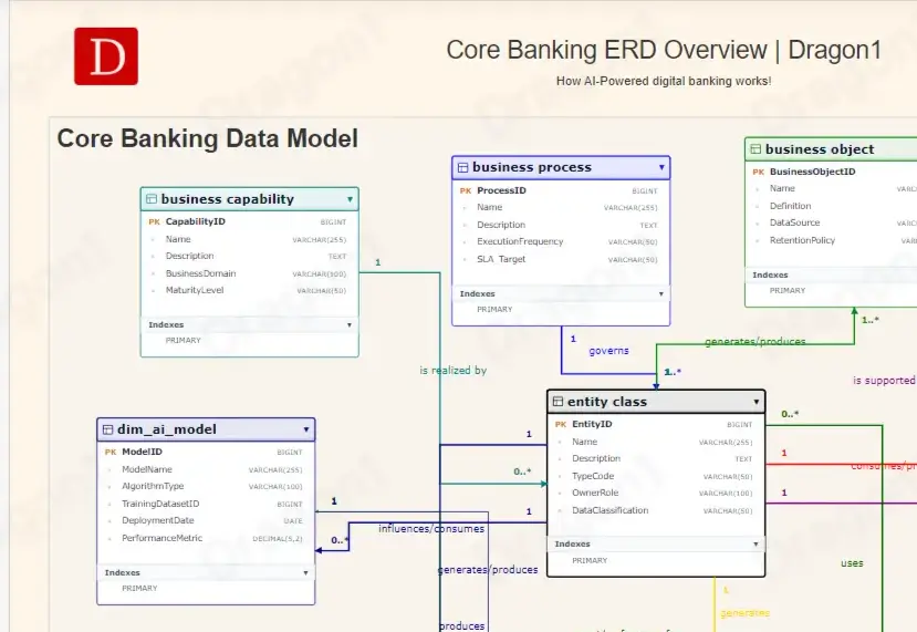
Entity Relationship Diagram ERD does not exist in isolation. Within modern enterprises, an ERD is one of several architectural viewpoints that collectively describe how an organization operates. While Business Process Models explain how work is performed and Application Architectures describe which systems support the business, an ERD defines which information the enterprise depends on and how that information is structured.
For this reason, the Entity Relationship Diagram is a fundamental artifact within Enterprise Architecture, Information Architecture, Data Governance, and Enterprise Data Management.
ERD in Enterprise Architecture
Within Enterprise Architecture, information is treated as a strategic enterprise asset. Business processes, applications, and technologies continuously evolve, but enterprise information must remain consistent,
trustworthy, and reusable across the organization.
An ERD provides the logical representation of enterprise information. It establishes a common vocabulary shared by Business Analysts, Enterprise Architects, Data Architects, Software Engineers, and Database Administrators.
| Architectural Domain |
Relationship with the ERD |
| Business Architecture |
Business Objects, Business Rules, and Business Capabilities reference Entity Types. |
| Information Architecture |
Defines the logical structure of information. |
| Application Architecture |
Applications create, read, update, and delete Entity Types. |
| Integration Architecture |
APIs, messages, and events exchange Entity Types. |
| Technology Architecture |
Databases implement Entity Types as physical tables. |
An ERD therefore acts as the bridge between business knowledge and technical implementation.
ERD and Business Objects
Business Objects represent concepts that are meaningful to an organization, such as Customer, Contract, Product, or Employee. They describe the business view of enterprise information.
Although the terms Business Object and
Entity Type are sometimes used interchangeably, they represent different perspectives.
| Business Object |
Entity Type |
| Business concept. |
Logical information structure. |
| Business-oriented. |
Data-oriented. |
| Defined by business stakeholders. |
Defined by architects and data modelers. |
| Independent of implementation. |
Used for logical database design. |
Maintaining traceability between Business Objects and Entity Types enables organizations to align business architecture with information architecture.
ERD and Business Capabilities
Business Capabilities describe what an organization does independently of organizational structures, applications, or technologies. Every capability depends on one or more Entity Types.
| Business Capability |
Primary Entity Types |
| Customer Management |
Customer, Contact, Address |
| Sales Management |
Quote, Order, Product |
| Procurement |
Supplier, Contract, Purchase Order |
| Human Resources |
Employee, Position, Contract |
| Asset Management |
Asset, Maintenance, Location |
Mapping Entity Types to Business Capabilities supports information ownership, governance, and enterprise-wide impact analysis.
ERD and Applications
Enterprise applications create, update, retrieve, and exchange information. An ERD helps determine which application owns specific Entity Types and where enterprise information is shared.
| Application |
Primary Entity Types |
| CRM |
Customer |
| ERP |
Product, Order |
| HRM |
Employee |
| Finance |
Invoice |
| Service Management |
Asset |
This mapping supports application rationalization, integration design, data ownership, and system modernization initiatives.
ERD and API Design
Modern enterprise applications expose information through Application Programming Interfaces (APIs). In API-first architectures, API resources are commonly derived directly from Entity Types defined in the logical data model.
Examples include:
- Customer API
- Product API
- Order API
- Invoice API
- Employee API
Designing APIs from a consistent ERD improves interoperability, simplifies integration, and establishes a shared enterprise vocabulary.
- Consistent resource definitions
- Reduced integration complexity
- Standardized business terminology
- Improved semantic interoperability
- Simplified API version management
ERD and Master Data Management (MDM)
Master Data Management (MDM) identifies, governs, and maintains the enterprise's most important business entities. An ERD provides the structural foundation for identifying these master entities and defining their relationships.
Typical Master Data entities include:
- Customer
- Product
- Employee
- Supplier
- Organization
- Location
A well-designed ERD helps organizations determine:
- The authoritative source of enterprise information.
- Ownership of Entity Types.
- Synchronization rules between applications.
- Responsibilities of Data Owners and Data Stewards.
Without a logical enterprise information model, Master Data Management initiatives often struggle to establish a reliable Single Source of Truth.
ERD and Data Governance
Data Governance defines the policies, responsibilities, and controls required to manage enterprise information throughout its lifecycle. The ERD provides the structural framework to which governance metadata can be attached.
Typical governance metadata includes:
- Data Owner
- Data Steward
- Security Classification
- Confidentiality Level
- Retention Period
- Privacy Classification
- Quality Metrics
- Regulatory Requirements
Integrating governance metadata with Entity Types improves compliance, accountability, and enterprise-wide data quality.
ERD and Data Lineage
Data Lineage describes how enterprise information flows through systems, integrations, and analytical platforms. An ERD identifies the logical Entity Types that participate in these information flows.
Customer
     │
     ▼
CRM
     │
     ▼
Integration Platform
     │
     ▼
Data Warehouse
     │
     ▼
Analytics Dashboard
     │
     ▼
AI Model
Combining ER Diagrams with Data Lineage enables organizations to perform:
- Change impact analysis
- Root cause analysis
- Audit tracing
- Regulatory compliance reporting.
- Data quality assessments
ERD and Cloud-Native Architectures
Cloud-native technologies have transformed deployment models, but they have not changed the need for logical enterprise information models. Regardless of where information is stored, organizations still require consistent definitions of their Entity Types and Relationships.
Logical ERDs remain independent of deployment platforms such as:
- Microsoft Azure SQL Database
- Amazon RDS
- Google Cloud SQL
- Oracle Autonomous Database
- PostgreSQL
- MySQL
Separating logical information models from implementation technology improves portability and reduces vendor lock-in.
ERD and Microservices
Microservice architectures often assign each service its own database, increasing autonomy but also introducing challenges related to information consistency and ownership.
Enterprise-level ERDs help maintain semantic consistency across distributed services by providing a common enterprise information model.
Common challenges include:
- Duplicate business entities
- Distributed ownership
- Synchronization complexity
- Event consistency
- Semantic fragmentation
An enterprise ERD reduces these risks by establishing standardized definitions for shared information.
ERD and Artificial Intelligence
Artificial Intelligence depends on high-quality enterprise information. Inconsistent logical data models frequently lead to poor-quality datasets, unreliable analytics, and inaccurate AI models.
A well-designed ERD contributes to AI readiness by providing:
- Consistent Entity Definitions.
- Standardized Attributes.
- Governed Relationships.
- Enterprise-wide semantics.
- Higher data quality.
Reliable AI begins with reliable enterprise information.
Entity Relationship Diagrams in Dragon1
Within Dragon1, an Entity Relationship Diagram is not treated as an isolated database model but as a reusable architectural artifact within the Enterprise Architecture Repository. Every Entity Type can be connected to Business Objects, Business Capabilities, Business Processes, Applications, APIs, Technologies, Requirements, Risks, Controls, and architectural principles.
This integrated approach transforms an ERD from static documentation into a living enterprise knowledge model that supports traceability, governance, and enterprise-wide impact analysis.
| Dragon1 Concept |
Relationship with an ERD |
| Business Object |
Represents the business meaning of an Entity Type. |
| Business Capability |
Uses or owns one or more Entity Types. |
| Business Process |
Creates, updates, or consumes Entity Instances. |
| Application |
Implements the logical information model. |
| API |
Publishes Entity Types as reusable enterprise resources. |
| Technology |
Hosts the physical implementation of the information model. |
| Requirement |
Defines functional or regulatory constraints. |
| Risk |
Identifies information-related business or technical risks. |
| Control |
Protects information quality, security, and compliance. |
Traceability
One of the greatest strengths of Enterprise Architecture is the ability to maintain traceability across all architectural domains. Within Dragon1, Entity Types are linked to every relevant architectural artifact, allowing architects to understand the impact of change before implementation begins.
Business Requirement
        │
        ▼
Business Capability
        │
        ▼
Business Process
        │
        ▼
Entity Type
        │
        ▼
Application
        │
        ▼
API
        │
        ▼
Database Table
        │
        ▼
Technology Platform
End-to-end traceability enables organizations to perform reliable impact analyses, identify dependencies, and improve governance across complex enterprise landscapes.
Benefits of an Enterprise ERD
A professionally maintained Entity Relationship Diagram provides significant long-term value beyond database design. It becomes a strategic asset that supports initiatives in architecture, governance, software engineering, and digital transformation.
- Establishes a shared enterprise vocabulary.
- Improves communication between business and IT.
- Reduces duplicate and inconsistent information.
- Supports Master Data Management initiatives.
- Improves data quality and consistency.
- Simplifies system integration.
- Supports cloud migration projects.
- Enables enterprise-wide impact analysis.
- Strengthens regulatory compliance.
- Provides a foundation for AI and analytics.
- Improves enterprise interoperability.
- Accelerates application modernization.
Best Practices
High-quality Entity Relationship Diagrams are the result of disciplined modeling practices. The following recommendations help organizations develop reusable, maintainable, and technology-independent information models.
- Model business concepts before designing database tables.
- Use meaningful and consistent Entity Type names.
- Clearly define every Attribute and Relationship.
- Normalize information where appropriate.
- Capture business rules explicitly.
- Separate conceptual, logical, and physical models.
- Maintain traceability between architectural viewpoints.
- Assign ownership to every critical Entity Type.
- Version and govern enterprise information models.
- Keep the ERD synchronized with enterprise architecture repositories.
Advanced Entity Relationship ER Model
As enterprise information landscapes become increasingly distributed, interconnected, and governed, Entity Relationship Diagrams evolve beyond traditional database modeling. Modern Entity Relationship ER Diagrams support enterprise-wide information management by integrating conceptual modeling, metadata, governance, interoperability, and architecture.
This section introduces advanced concepts that are commonly encountered in Enterprise Architecture, Information Architecture, and large-scale software engineering.
Entity Type versus Business Object
Although the terms Entity Type and Business Object are frequently used interchangeably, they describe different viewpoints of the same business concept.
A Business Object represents the meaning of a concept from a business perspective, while an Entity Type describes the logical structure required to store and manage information about that concept.
| Business Object |
Entity Type |
| Business concept |
Logical information structure |
| Business terminology |
Information terminology |
| Business-oriented |
Data-oriented |
| Used by business stakeholders |
Used by architects and engineers |
| Independent of implementation |
Foundation for logical database design |
Canonical Data Model
A Canonical Data Model (CDM) provides a standardized, enterprise-wide representation of information that is shared across multiple applications and integration platforms.
Instead of allowing every application to define its own interpretation of concepts such as Customer, Product, or Order, the Canonical Data Model establishes a single enterprise definition.
Logical Entity Types defined within an ERD frequently serve as the foundation for a Canonical Data Model.
Benefits
- Reduced integration complexity
- Consistent enterprise terminology
- Simplified API development
- Improved interoperability
- Reduced transformation logic
Semantic Data Model
A Semantic Data Model extends the traditional ERD by explicitly defining the meaning of Entity Types, Attributes, and Relationships. It captures not only structure, but also semantics.
Semantic models are increasingly important for enterprise search, interoperability, artificial intelligence, and knowledge management.
| Traditional ERD |
Semantic Data Model |
| Describes structure. |
Describes structure and meaning. |
| Focuses on entities. |
Focuses on enterprise concepts. |
| Database-oriented. |
Knowledge-oriented. |
Ontology versus ERD
Both ERDs and ontologies describe relationships between concepts, but they serve different purposes.
| Entity Relationship E R Diagram |
Ontology |
| Logical information model. |
Knowledge representation model. |
| Supports database design. |
Supports reasoning and inference. |
| Focuses on persistence. |
Focuses on semantics. |
| Common in software engineering. |
Common in AI and knowledge engineering. |
Enterprise knowledge platforms increasingly combine ERDs with ontologies to provide richer semantic context.
Knowledge Graphs and ERDs
Knowledge Graphs model entities and relationships as interconnected nodes and edges. While an ERD focuses on the logical structure of enterprise information, a Knowledge Graph emphasizes discoverability, semantic relationships, and knowledge inference.
Many organizations derive Knowledge Graphs from an existing enterprise Entity Relationship ER Model to improve search, analytics, and AI-driven decision support.
Property Graphs versus Entity Relationship Diagrams ERDs
Although Entity Relationship Diagrams and Property Graphs both model entities and relationships, they are based on different architectural principles and are optimized for different types of workloads.
| Entity Relationship E R Diagram |
Property Graph |
| Relational information model. |
Graph-based information model. |
| Optimized for transactional systems. |
Optimized for highly connected data. |
| Relationships implemented through foreign keys. |
Relationships are first-class graph objects. |
| Excellent for structured enterprise data. |
Excellent for network analysis and recommendations. |
| Commonly implemented in SQL databases. |
Commonly implemented in graph databases. |
Property Graphs complement rather than replace Entity Relationship Diagrams. Many enterprise solutions maintain an ERD as the authoritative logical information model while using graph technologies for advanced analytics and relationship discovery.
ERD and Domain-Driven Design (DDD)
Domain-Driven Design organizes enterprise software around business domains and bounded contexts. Within each bounded context, Entity Types describe the persistent information required to support domain behavior.
While a traditional enterprise ERD provides an organization-wide information model, Domain-Driven Design intentionally limits the scope of a model to a specific business domain.
Relationship between ERD and DDD
- Enterprise ERDs provide enterprise-wide consistency.
- Bounded Contexts define local information ownership.
- Shared Entity Types require governance across domains.
- Canonical definitions reduce semantic conflicts.
- Traceability supports enterprise integration.
ERD and Data Mesh
Data Mesh promotes decentralized ownership of analytical data products. Although ownership is distributed, organizations still require a common enterprise vocabulary and consistent definitions of core Entity Types.
Enterprise ERDs provide this shared semantic foundation while allowing individual domains to evolve independently.
| Enterprise ERD |
Data Mesh |
| Enterprise-wide logical model. |
Domain-owned analytical models. |
| Central semantic consistency. |
Decentralized implementation. |
| Shared enterprise concepts. |
Autonomous data products. |
ERD and Digital Twins
Digital Twins create virtual representations of physical assets, organizations, or business operations. The underlying information model of a Digital Twin frequently originates from an Entity Relationship E R Diagram.
Entity Types define the objects represented within the Digital Twin, while Relationships describe structural dependencies between those objects.
As telemetry and operational data are added, the logical ERD evolves into a living enterprise information model that supports simulation, monitoring, and predictive analytics.
ERD Governance and Lifecycle Management
Enterprise information models are not static documents. As business processes, applications, regulations, and technologies evolve, Entity Relationship Diagrams must evolve as well. Effective governance ensures that the logical information model remains accurate, consistent, and aligned with business objectives throughout its lifecycle.
Organizations should establish formal processes for reviewing, approving, versioning, and maintaining Entity Relationship Diagrams. Every structural change should be traceable to a business requirement, architectural decision, or regulatory obligation.
Recommended governance practices
- Assign ownership to every Entity Type.
- Maintain a controlled enterprise glossary.
- Version every logical data model.
- Review models during architecture governance.
- Maintain traceability to business requirements.
- Validate models before implementation.
- Synchronize logical and physical data models.
- Document architectural decisions.
- Archive obsolete model versions.
- Continuously monitor model quality.
Common Modeling Mistakes
Poorly designed Entity Relationship Diagrams frequently become the root cause of data quality issues, integration complexity, and software maintenance problems. Many of these issues originate during logical modeling rather than during database implementation.
| Modeling Mistake |
Potential Consequence |
| Duplicate Entity Types |
Conflicting definitions and duplicate data. |
| Missing business rules |
Inconsistent application behavior. |
| Incorrect cardinality |
Invalid relationships and integrity issues. |
| Poor naming conventions |
Reduced readability and maintainability. |
| Mixing conceptual and physical models |
Technology-dependent logical models. |
| Missing metadata |
Weak governance and limited traceability. |
| No ownership assigned |
Unclear accountability for enterprise data. |
Key Takeaways
- An ERD describes the logical structure of enterprise information.
- Entity Types, Attributes and Relationships form the foundation of information architecture.
- Business Rules, Cardinality and Integrity Constraints ensure consistency.
- ERDs support database design, application integration, APIs and analytics.
- Logical data models remain independent of implementation technologies.
- Enterprise-wide ERDs improve governance, interoperability and traceability.
- Modern ERDs support cloud-native architectures, AI, Data Mesh and Digital Twins.
- Within Dragon1, ERDs are integrated with Business Architecture, Application Architecture and the Enterprise Metamodel.
Get Started
The Entity Relationship Diagram ERD remains one of the most important modeling techniques for designing and governing enterprise information. Although originally developed to support relational database design, its value now extends far beyond databases.
A modern ERD provides a technology-independent description of business information that enables architects, analysts, and engineers to establish a shared understanding of enterprise data. It serves as the foundation for information architecture, application integration, data governance, master data management, analytics, and artificial intelligence.
Within Dragon1, the Entity Relationship Diagram is treated as an architectural building block rather than an isolated database artifact. By connecting Entity Types to Business Capabilities, Business Processes, Applications, APIs, Technologies, Requirements, and Governance concepts, Dragon1 enables organizations to transform logical data models into enterprise knowledge models that support traceability, impact analysis, and informed decision-making.