HOW TO Create an Enterprise Architecture Blueprint
This page introduces how to create and generate an EA Blueprint data driven on Dragon1, in three ways: via the Viewer, via Excel Sheets and via the Data Manager.
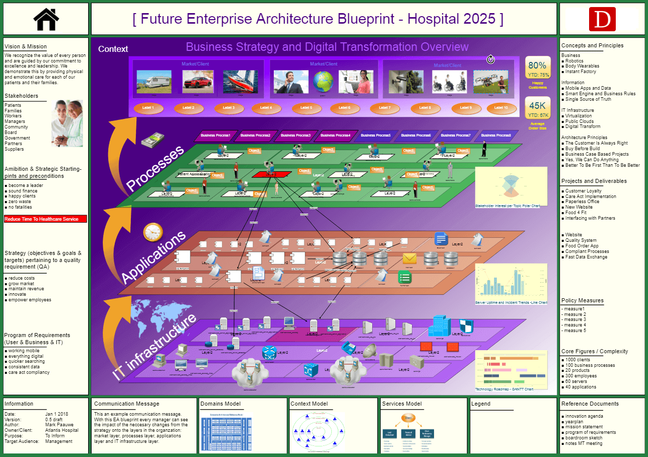
Example Enterprise Architecture Blueprint
The visualization blow is an example of a generated data-driven enterprise architecture blueprint on Dragon1. An overview like this is necessary in any organization.
Dragon1 Viewer
This section explains how to create an Enterprise Architecture Blueprint using the Dragon1 Viewer for drawing.
Creating a blueprint via the Viewer is basically done via the following steps:
- Step 1 : Go to the Dragon1 Viewer
- Step 2 : Create an atlas
- Step 3 : Select a page and visualization template
- Step 4 : Edit/customize the template
- Step 5 : Enter/import data
- Step 6 : Populate the template/link the data to the template
- Step 7 : Add Views, Widgets and Button
- Step 8 : Export or Save
The steps are detailed below.
Step1: Go to the Dragon1 Viewer
First, go to the Dragon1.
Step 2: Create an atlas
Step 3: Select a page and visualization template
Step 4: Edit/customize the template
Step 5: Enter/import data
Step 6: Populate the template/link the data to the template
Step 7: Add Views, Widgets and Button
Step 8: Export or Save
Excel Sheet
This section explains how to generate an Enterprise Architecture Blueprint via uploading an Excel Sheet in the Dragon1 Viewer
Generating a blueprint by uploading an Excel Sheet is basically done via the following steps:
- Step 1 : Go to the workplace or tutorials
- Step 2 : Download a preformatted Dragon1 Excel Sheet
- Step 3 : Open Excel and edit the example
- Step 4 : Edit/customize the template
- Step 5 : Add/edit data
- Step 6 : Add/edit views and buttons
- Step 7 : Add Views, Widgets and Buttons
- Step 8 : Upload the Excel Sheet in the Viewer
The steps are detailed below.
Step1: Go to the workplace or tutorials
First, go to the workplace or tutorials overview.
Step 2: Download a preformatted Dragon1 Excel Sheet
Step 3: Open Excel and edit the example
Step 4: Edit/customize the template
Step 5: Add/edit data
Step 6: Add/edit views and buttons
Step 7: Add Views, Widgets and Buttons
Step 8: Upload the Excel Sheet in the Viewer
Data Manager
This section explains how to create an EA blueprint via creating structures and data in the Data Manager.
Creating a blueprint via the Data Manager is basically done via the following steps:
- Step 1 : Go to the Data Manager
- Step 2 : Create an atlas, folder and page
- Step 3 : Create a visualization and link a template and model
- Step 4 : Edit/customize the template
- Step 5 : Add/edit data
- Step 6 : Add/edit views and buttons
- Step 7 : Add Views, Widgets and Buttons
- Step 8 : View the visualization in the viewer
The steps are detailed below.
You will create this blueprint by using one web application on Dragon1: The Visual Designer.
You will take the following steps:
- Create a dossier structure
- Enter Data
- Create process and application models, using the data
- Create links between the process and application models
- Create process and application views, using the models
- Create links between views
- Create a visualization, using the views
- Publish the visualization to the Viewer to have it commented on by stakeholders
Step 1. - Create a Dossier Structure
First we are going to create a dossier structure in a cabinet to store our data.
To create a dossier structure
- Go to the Architecture Repository
- Create or open a Cabinet
- Select the cabinet in the Explorer treeview
- Create a dossier
- Create four folders in the dossier: Data, Model, View, and Visualization
Screenshot of a cabinet with created folders.
Step 2. - Enter Data
On Dragon1 you can enter data by dragging shapes to a folder.
To enter data
- Go to the Visual Designer
- Create or open a Cabinet
- Select a folder
- Insert shapes from the Draw Archifact or Draw Entity dropdown menu
- For the process-application landscape choose the shapes for three layers:
- Business Layer: Group, Function, Process, Activity
- Information Layer: Information Object
- Application Layer: Application, Database, Interface, Service
- Select a shape in the treeview
- Select the shapes' icon on the canvas
- Change the name of the shape at the right top in the text attributes of the Inspector
Screenshot of a cabinet with entered data.
Step 3. - Create a Model, using the data
To create a model
- Go to the Visual Designer
- Create or open a Cabinet
- Select a folder
- Insert models from the menu bar
- Create models for the process-application landscape for every entity class you have used
- Process model, Service model, Application model, etc...
- Enter a name for the model
- Optionally choose a type for the model
- Insert shapes like processes and applications for the model by clicking on Draw Archifact or Draw entity and drag the shape onto the canvas
- You can change the color and size of the shapes
- Draw connections between the shapes using the smart tools of a selected shape.
Screenshot of a cabinet with a model.
Step 4. - Create links between models
To create a link between models:
- Select a model in the Explorer treeview
- Select a shape in the model
- Enter a link to another model in the LinkURL field of the text attributes
Step 5. - Create a View, using the model
To create a view
- Go to the Visual Designer
- Create or open a Cabinet
- Select a folder
- Insert views from the menubar
- Create views for the process-application landscape for each model you created:
- Functions view, Process view, Activities view, etc...
- Enter a name
- Select the model to use
- Enter a viewing rule for the model data:
- Rule Event: onload
- Rule Condition: Class=Process;Name=Sales;Relation=FirstLevel
- Rule Action: Show(name)
Step 6. - Create links between views
To create a link between views:
- Select a view in the Explorer treeview
- Select a shape in the view
- Enter a link to another view in the LinkURL field of the text attributes
Step 7. - Create a Visualization, using the views
To create a visualization
- Go to the Visual Designer
- Create or open a Cabinet
- Select a folder
- Insert a visualization from the menubar
- Drag a shape on the canvas. You will use this shape to generate the view data on the canvas.
- For the process-application landscape use three shapes:
- One for Functions, Processes and Activities.
- Save the visualization
- Select one of the three view shapes
- Enter the following view rules in the data attributes panel of the inspector.
- Rule Event: onload
- Rule Condition: Class=Process
- Rule Action: Show(name)
Do this for all three view shapes
With this rule you will only see the processes from the view data. You can also show the whole view with Rule Condition = *.
Step 8. - Publish the visualization
To publish a visualization:
- Select a visualization in a folder
- Click on the Share button in the menubar
- Enter the correct data in the dialog
- Click on the share button in the dialog
- Now go to the Viewer and search for your visualization by its title
- Add a comment to the visualization
- Filter the visualization on certain values
Interesting Things to Discover
Discover more pages to help you discover interesting things you can do with Dragon1 software.