Create A Use Case Diagram
On this page, you will learn how to create a static use case diagram.
With static, you draw a picture without an underlying separation of data, model, and view. Using models and views is, of course, the preferred way of creating architectural visualizations. To learn Dragon1 a bit, it is wise first to create static use case diagrams.
We have pre-selected the Use Case shapes for you in the Visual Designer. Below there are ten easy steps for drawing useful Use Case Diagram examples.
Here it goes!
To draw STATIC, a Use Case Diagram follows all the next steps. This lesson takes about 15 minutes to complete. When you are finished, you have created a simple Use Case diagram example from scratch.
What is a Use Case Diagram?
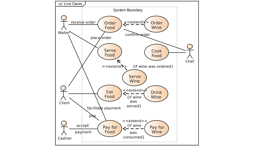
Use Case Diagrams are essential to UML, the Unified Modeling Language. A use case diagram or use case model is a design, schema, or description of a system from an external usage viewpoint. This is instead of designing and drawing the system from a developer's perspective. Writing use cases is a deciding factor in building a system that meets the users' needs.
An actor in a use case is someone or something using a system. A use case in a use case diagram is a business goal, objective, function, task, or activity.
Preparation
- Login and start the Visual Designer
- Create a new cabinet or open an existing cabinet
- Create a new dossier or expand an existing dossier
- Create a new folder or select an existing folder
- Insert a visualization, a use case template, in this folder by clicking on Insert Visualization in the Button bar
- The New Edit dialog appears. Provide a name for the visualization. Something like 'New Coffee Machine'
- Click OK. You now see the Use Case Diagram added in the Explorer Treeview
Setup
- Make sure you have the visualization entity selected in the Explorer tree view.
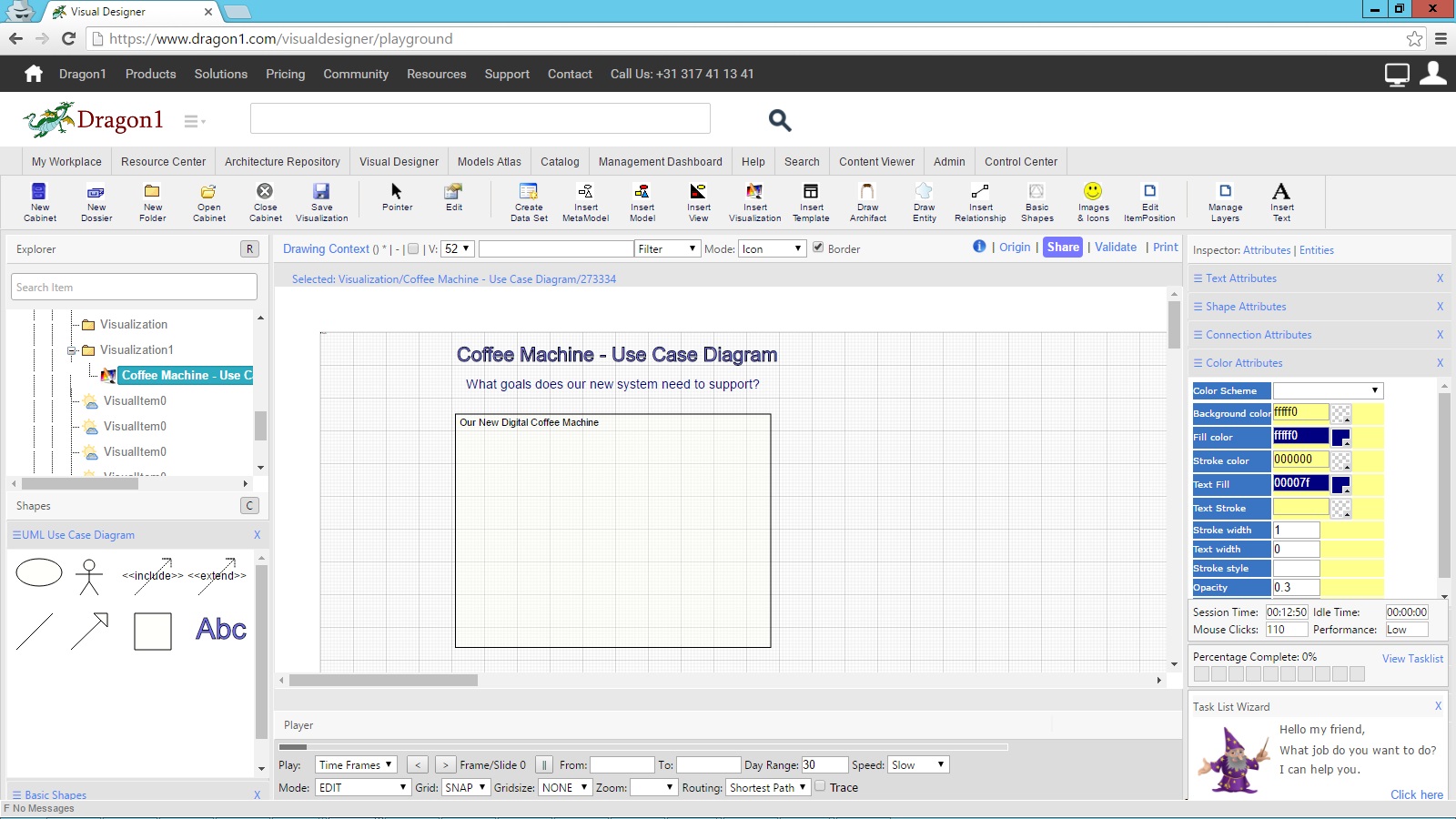
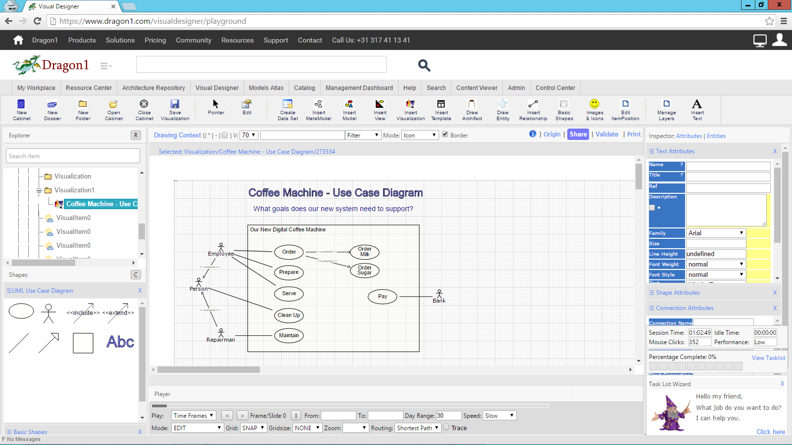
- Now drag the ABC shape to the canvas to create a title element on the Diagram
- Expand the Text Attributes panel in the Inspector on the right by clicking the panel's name.
- Make sure the Abc text element is still selected.
- Enter a title for the diagram in the title field of the Text attributes panel. Something like 'Coffee Machine - Use Case Diagram'
- Drag a second 'Abc' element to the canvas.
- Enter a subtitle for the diagram. For instance, write down a question that must be answered with this use case diagram example. Use this question as a subtitle on the diagram.
- Drag a square shape to the canvas and give it the title of the system you are designing. For instance, a coffee machine.
- Shape this square as a rectangle. It will be your system boundary or scope for your system. Your system must fulfill any use case that is required. Any use case placed outside the scope of your system is out of the scope of your system. Make use of this option. It is as easy as that.
Drawing Actors
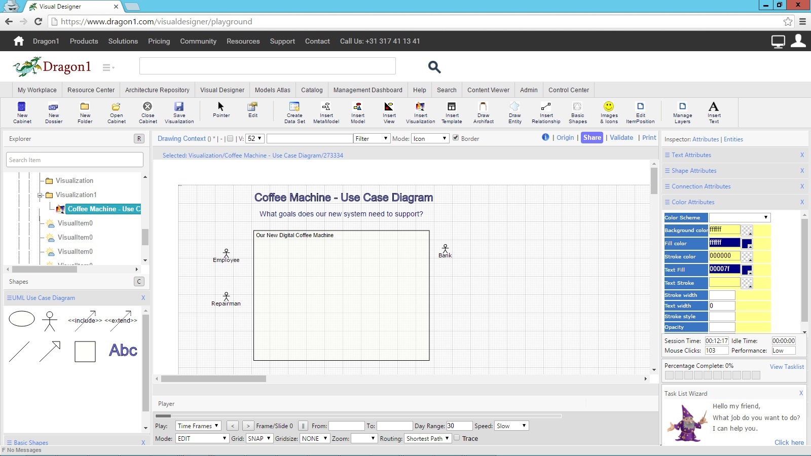
- Drag an actor shape from the shapes panel. Do this three times
- You see, every time you add a shape, the visualization is automatically saved. This will prevent any loss of data. If you prefer, you can turn off this behavior in your settings.
- You can also duplicate a shape by clicking the plus sign in the smart tools shown above a shape when it is selected.
- Expand the Text Attributes panel in the Inspector on the right
- Enter a title for the actor in the title field. For instance: Employee, Repairman, Bank
- You can also edit the title of a shape by double-clicking on it. Tip: Type in your letters slowly when editing inline. Also, you can press 'Enter' to create a multiline title.
Drawing Use Cases with Associations
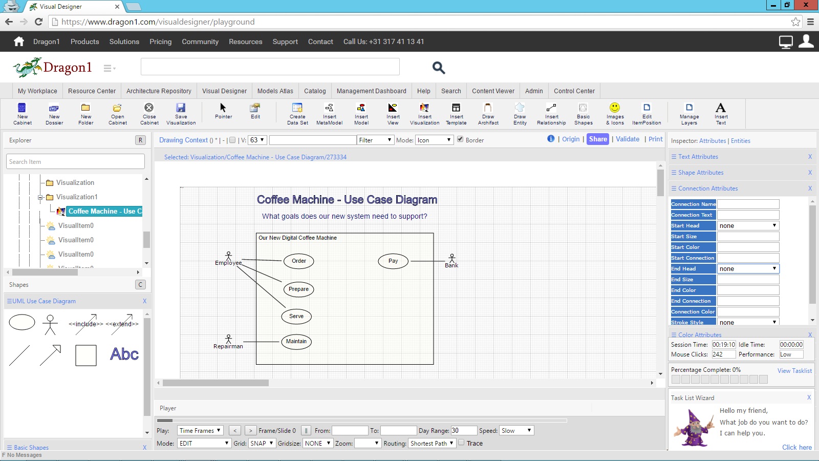
- Drag a use case shape from the shapes panel. Do this five times.
- Give the use case shapes the following titles: Order, Prepare, Serve, Maintain, and Pay.
- A use case is about actors and systems doing something. Think of it like functions or actions: An employee orders Coffee when he is thirsty. The machine prepares to make the coffee. The repairman wants to do maintenance, etc.
- Now draw connections from the actor shapes to the corresponding use case shapes. Do this by selecting an actor shape, dragging the > button from the Smart Tool to the use case, and then releasing the mouse button.
- This simple line is called an association.
- Now, a connection is drawn. If you have attached the shapes correctly, you can move them around, and the connections will follow.
- If a shape is not attached, you can select the head of a connection, draw it over a shape, and let go of the mouse button.
- Also, you can change the connection flow by clicking on a line segment and dragging it. Try it out and see for yourself how nice it works.
Extending Use Cases with <<extend>> Dependencies
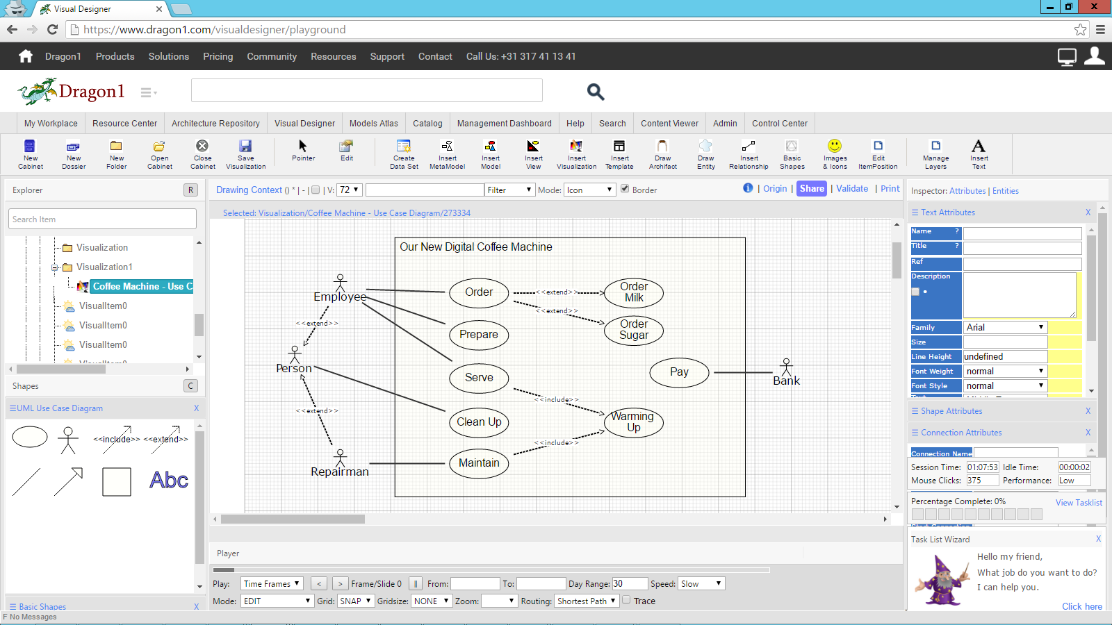
(When I order coffee, sometimes I order sugar and milk if I feel like it. This is an example of extending)- Suppose the Employee and Repairman can run a cleanup program on the coffee machine. Then, they share the same behavior. In a use case, you can place this in a separate use case with an extended relationship. We are going to do that now.
- Add an actor shape on the canvas by selecting an actor, clicking on the plus sign, and moving the new shape to its correct place.
- Give the shape the title: Person.
- Drag the extended dependency from the shapes panel and draw connections from the Employee and Repairman to Person.
- This type of connection or relationship is called a dependency
- Now draw two extra use cases for ordering sugar and milk. And draw extended dependencies.
Include Use Cases with <<include>> Dependencies
(When a machine makes coffee, it must take in water. This is an example of include)- Suppose that several use cases share a common task. You can create a new use case and include that one in the first two use cases.
- In a coffee machine, warming up is a task shared by the use case serve and the maintenance program. So, draw a new use case and two <<include>> dependencies.
Use Generalization
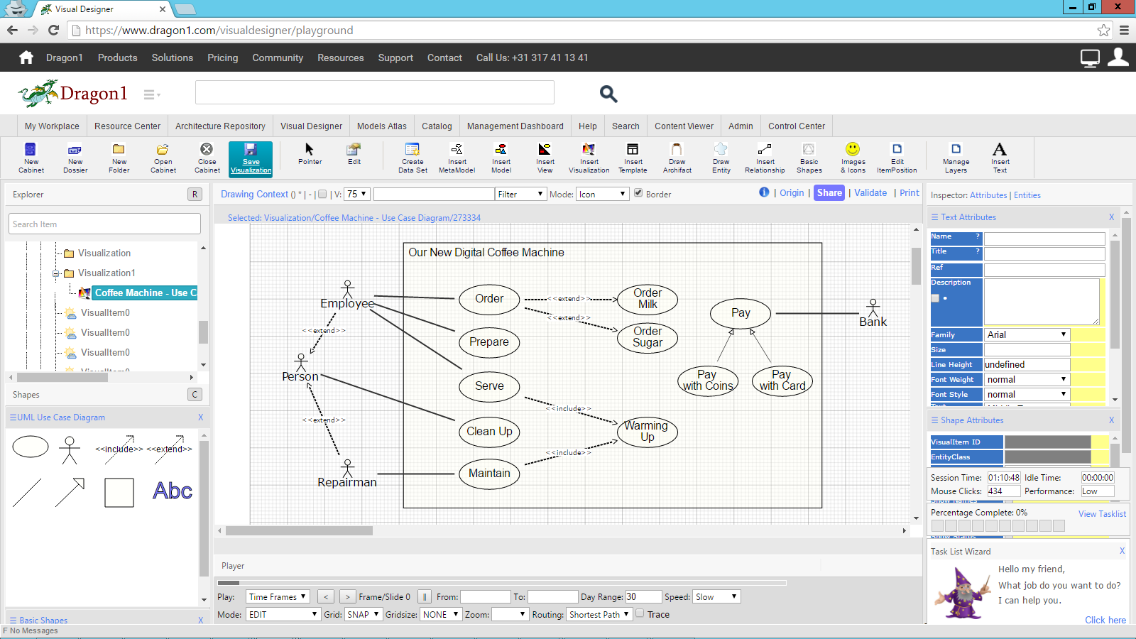
If you have a coffee machine, you might want to support various payment systems with coins and cards.
In that case, you can create a generic use case and two specialized use cases with a generalization to the generic use case.
- Draw three new use cases. Please give them the titles: Pay, Pay with Coins, and Pay with Card.
Saving, Printing, Sharing, and Presenting
- To save your diagram's version, click the Save Visualization button in the button bar.
- To print the use case, click Print in the top middle bar of your screen above the drawing context. A printer-friendly version of your screen is shown. From there, follow the browser's printing features.
- To share diagram examples, click the share link next to the print link. Fill in the share data in the dialog and click OK. You have now shared your use case diagram example in a channel on Dragon1, if you have chosen the publication status as 'worldwide'.
- Search for your diagram in the search bar of the Dragon1 website and check if your diagram communicates what you want.
- To present your diagram, go to the Viewer and search for your diagram.
- Switch to presentation mode and do your presentation with the use case examples on Dragon1.
Use the different association options, like extend, include, and generalization, in a smart way to make your system less complex and your diagrams more understandable.
For more information about Use Cases, please read the UML books available anywhere or contact us. We have tons of examples to share with you.
Also, try the DEMO generating an use case diagram by importing Excel data.


